
1x5A Motor Controller (6-24V Input, 9A Burst)
SKU:


This motor speed controller is a compact, easy way to proportionally control the speed and direction of a brushed DC motor! Just plug in your motor, a battery (between 6V and 24V), and a receiver to get your motor moving.
Wiring
- Receiver
If you are using an R/C receiver, simply plug this 3-wire connector into the desired channel. The built-in 5V BEC (which can supply 500mA continually) will power your receiver via the red wire. It can also be plugged into a servo controller or an Arduino (via jumper wires) or anything that can produce a PWM signal. It responds proportionally to a signal between 1100 - 1900 microseconds. This range was chosen to allow most standard radio systems to achieve the full motor power without reprogramming. - 6-24V In
Plug a battery or power supply into the XT30 connector. XT30 connectors are keyed, which prevents them from being plugged in backward. - Motor
If you are rocking a motor that has 3.5mm bullet connectors, just plug it in! If your motor does not have bullet connectors, check out our bullet connector lead. Brushed DC motors are reversible so you don't need to worry about plugging it in backwards. If the motor spins the wrong direction, just swap the red and black wires.
Mounting
Most motor controllers this small offer no way to fasten them with screws. This one has a single mounting hole sized for an M4 screw, making it easy to bolt down to goBILDA® components or screw into wood with a #6 wood screw. When screwed down to a metal surface, the motor controller uses that contact as a heat sink, improving thermal performance. Its small size, low mass, and slender footprint also make it a good candidate for zip ties or even double-sided foam tape if that better suits your build style.
Using with Motors Rated Above 5A Stall Current
It is generally best practice to choose a motor controller whose continuous current rating can handle a motor's stall current. However, this controller is still safe to use with motors that exceed its current ratings. The controller continuously monitors its own temperature and current limits, then adjusts the output to deliver as much power as safely possible. It can sustain its full 9A burst current indefinitely as long as temperatures stay within range. As things heat up, it dynamically lowers the current limit to protect itself, so no matter how much the motor tries to draw or how high you set the power, the controller will never exceed safe levels. How much this affects real-world performance depends on the load. The controller is designed to dissipate heat through its mounting lug into your project's structure. Mounting to aluminum or other thermally conductive material will provide a measurable increase in performance. If the motor only occasionally pushes past the 5A continuous and 9A burst ratings, you are unlikely to notice any throttling at all. The stall current of a Yellow Jacket Planetary Gear Motor lines up well with this controller's burst rating, so in most typical uses the two can be paired without any noticeable impact on performance.
Protection
The board has safety features built in to protect it from silly wiring errors and/or punishment beyond what it should be asked to withstand. While the XT30 connector itself is keyed, we know that sometimes input connectors get removed and/or replaced, so we added reverse-voltage protection. The board also has over-current protection that will kick in if your motor is pulling so much current that there's a risk of damaging the board. In a similar fashion, if the motor controller gets too hot, it will throttle the current until the temperature reduces to a reasonable level.
Safety Features
- Reverse-Voltage Protection
- Over-Current / Short-Circuit Protection
- Over-Temperature Protection
- Signal Arm Zone
Status LED
The status LED communicates the motor controller's status via Blink Codes. These light sequences are colored according to Good, Warning, and Fault statuses, and their blinks help to indicate Over-Temperature and Over-Current events, as well as signal and arming statuses. Refer to this chart to know the specific status communicated by each possible pairing of color and Blink Code.
| Color Code | Blink Code |
|---|---|
| Green: Good |
Solid: Armed Slow Single Blinks: Unarmed |
| Orange: Warning |
Slow Single Blinks: No Signal Double Blinks: Over-Temperature Triple Blinks: Over-Current |
| Red: Fault |
Fast Double Blinks: Over-Temperature Fast Triple Blinks: Over-Current |
Downloads
Specs
| Weight | 19g |
|---|---|
| Compatible Motor Type | Brushed DC |
| Channels | 1 |
| Motor Ports | 1 per Channel |
| Voltage Range | 6 - 24V (2 - 6S) |
| Continuous Current | 5A |
| Burst Current | 9A |
| Burst Duration | ≈15s (Temperature Dependent) |
| Power Connector | XT30 (FH-MC) |
| Motor Connector | 3.5mm Bullet (MH-FC) |
| Signal Connector | 2.54mm (0.1") Pitch Female (TJC8) |
| Signal Input | R/C PWM |
| Signal Voltage | 3.3 - 5V |
| PWM Range | 1100µs - 1900µs |
| PWM Center + Deadband | 1500µs ±10µs |
| PWM Arm Zone | 1500µs ±100µs |
| BEC Voltage | 5V |
| BEC Current | 500mA |
| BEC Burst Current | 1A |
Related Products:
These products have been hand curated by our R&D team. We have selected products that are directly compatible with or very relevant to the 3105-0101-0005.








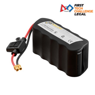

![3100-0006-0003 - (6V, 3000mAh, XT30 Connector [MH-FC], 20A Fuse, 6-3)](https://cdn11.bigcommerce.com/s-x56mtydx1w/images/stencil/318x318/products/1163/5818/3100-0006-0003__25708__75076.1701992657.jpg?c=1 "3100-0006-0003 - (6V, 3000mAh, XT30 Connector [MH-FC], 20A Fuse, 6-3)")